

Photometric Design for Hazardous Locations: Choosing Lumen Output
Use mounting height and replacement benchmarks to screen an industrial LED lumen range, then prove the layout with the exact model’s IES file.
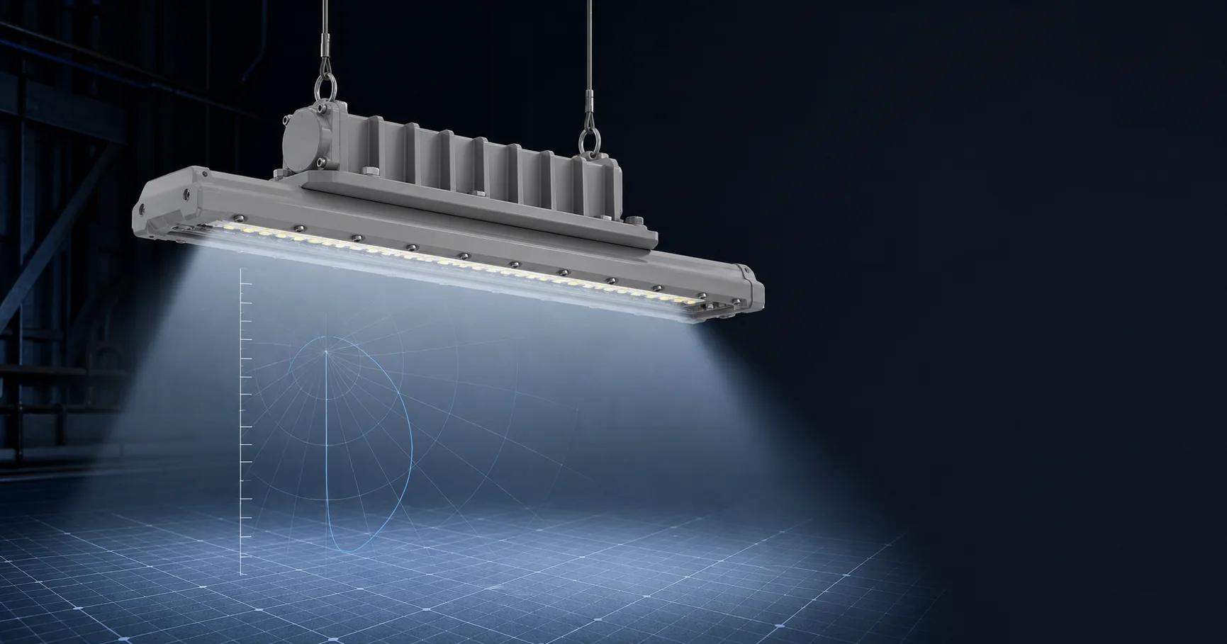
Choose industrial LED lumen output from the maintained lux or foot-candle target, mounting height, optic, fixture spacing and expected light loss. Use the selector below to screen LEDEX lumen packages, then run the exact model’s IES file to test minimum, average and vertical illuminance before issuing a fixture schedule.
The short version: lumens tell you how much light leaves a source. Lux and foot-candles tell you how much reaches a surface. A mounting-height chart can establish a useful starting range, but only a photometric model can show where that light lands in the real room.
Preliminary lumen selector
Screen the right output range
Choose the closest starting condition. The result narrows the catalogue; it does not replace an IES calculation.
| Mounting height | Screening output | Typical starting use | Candidate LEDEX families |
|---|---|---|---|
| 8–12 ft2.4–3.7 m | 1,500–5,100 lm | Low bays, task zones, compact linear runs | |
| 12–15 ft3.7–4.6 m | 5,100–7,650 lm | Linear aisles, low bays, short-area floods | |
| 15–20 ft4.6–6.1 m | 9,600–13,600 lm | Process floors, platforms, medium bays | |
| 20–30 ft6.1–9.1 m | 13,600–25,500 lm | High bays, production halls, open process areas | |
| 30–40 ft9.1–12.2 m | 25,500–32,000 lm | Tall bays, large maintenance and storage areas | |
| 40+ ft12.2+ m | 48,000–90,000 lm | Very tall or broad areas requiring engineered opticsEngineering review |
Mounting height
8–12 ft
2.4–3.7 m
Low bays, task zones, compact linear runs
Mounting height
12–15 ft
3.7–4.6 m
Linear aisles, low bays, short-area floods
Mounting height
15–20 ft
4.6–6.1 m
Process floors, platforms, medium bays
Mounting height
20–30 ft
6.1–9.1 m
High bays, production halls, open process areas
Mounting height
30–40 ft
9.1–12.2 m
Tall bays, large maintenance and storage areas
Mounting height
40+ ft
12.2+ m
Very tall or broad areas requiring engineered optics
Product links are candidates only. Confirm the exact model marking, optic, ambient range, mount, voltage and IES file.
Lumens, lux, foot-candles and watts solve different questions
A strong lighting schedule keeps four quantities separate:
- Lumens (lm) describe luminous flux leaving the luminaire. They are an output value, not a work-plane result.
- Lux (lx) describe illuminance in lumens per square metre. One lux equals one lumen per square metre.
- Foot-candles (fc) describe illuminance in lumens per square foot. One foot-candle is about 10.764 lux. The IES definition of foot-candle provides the formal unit relationship.
- Watts (W) describe electrical input. Watts affect circuit loading and energy use, but they do not state where the emitted light will go.
A 15,000-lumen narrow distribution and a 15,000-lumen wide distribution can produce very different minimum illuminance, vertical light and glare. The housing, lens, reflector, optic and mounting orientation shape the result. This is why a watt-for-watt replacement or a blanket lumens-per-square-foot rule is too weak for a specification.
Start with the lighting task, not a catalogue number
Before filtering fixtures, define what people must see. A loading aisle, colour-inspection station, valve face, stair landing and open storage bay do not share the same visual task. Record the maintained horizontal illuminance on the relevant work plane, any vertical illuminance needed on equipment faces, the acceptable uniformity and any glare or colour-quality constraints.
The target should come from the owner’s operating needs, the project lighting professional and the applicable criteria for the task. The IES Illuminance Selector is designed to help practitioners locate recommendations in current IES documents. The CCOHS lighting survey guidance also explains why measurements need to reflect the work area and the task being assessed. Neither source turns one illuminance number into a universal answer for every industrial room.
Write the criteria into the design brief before choosing the lumen package. If the owner has not set them, mark them as an open design input instead of burying an assumption inside the fixture count.
Use mounting height to screen, not to approve
Mounting height changes the size and intensity of the light pattern at the work plane. Higher mounting usually calls for more output or a more controlled distribution, but room proportions, spacing, aiming and surface reflectance can change that relationship quickly.
The mounting-height tab above maps common industrial heights to lumen ranges available across current LEDEX families. It is deliberately a range. A 20-foot installation at the edge of a small bright room and a 20-foot installation above dark process equipment can require different optics, quantities and outputs.
Treat each linked product as a family to investigate. Before it enters a schedule, verify the exact catalogue number’s Canadian approval, hazardous-location marking, gas or dust group, temperature code, ambient range, voltage, mount, entries, accessories and photometric file. A family name is not the certification record.
Why the 40-foot band requires more engineering
At 40 feet and above, high output can increase glare while still leaving weak vertical illumination or dark areas behind structures. Modular flood and high-bay systems also offer distributions that cannot be compared by lumen total alone. Model the candidate optics, aiming and mounting points before deciding that the largest package is the safest choice.
Replacing HID or fluorescent lighting
Legacy lamp wattage is useful when the existing installation is the only available field reference. It is still a benchmark, not a one-step conversion. The HID and fluorescent tabs reproduce the lumen ranges in Eaton’s published hazardous-area LED lumen selection chart, including 400 to 500 W HID at 13,000 to 15,000 lumens and a four-lamp T5HO fixture at 17,000 lumens.
Before applying a replacement range, inspect the installation:
- Record the lamp and ballast, input wattage, reflector and lens.
- Note failed lamps, ballast losses, dirt, yellowed lenses and damaged reflectors.
- Measure representative illuminance with normal process equipment in place.
- Confirm the owner’s required maintained result, not only the degraded existing level.
- Compare the LED optic and spacing in a photometric model.
A lower-watt LED can outperform an aged HID system while using fewer lumens because the LED optic controls light more effectively and avoids some legacy optical losses. The reverse is also possible when a replacement has the wrong distribution or an obstructed mounting position.
The five inputs that control a credible lumen selection
1. Maintained illuminance
Specify whether the target is an average, a minimum or both. Record the horizontal work-plane height and any vertical planes at panels, gauges, labels, faces or equipment. Initial illuminance will decline as the system ages and accumulates dirt, so the calculation needs an agreed light-loss factor.
2. Room geometry and obstructions
Provide length, width, ceiling height, mounting height and fixture coordinates. Add tanks, ducts, structural steel, cranes, racks and process equipment that block or reflect light. An empty-room model can overstate performance in a dense process area.
3. Surface reflectance
Ceilings, walls, floors and equipment return part of the emitted light to the work plane. New white surfaces and aged industrial surfaces behave differently. Use project-specific reflectances when they are known and document any assumptions when they are not.
4. Optic, orientation and spacing
Photometric distribution decides how the lumen output is used. Wide distributions can improve uniformity at lower heights. Controlled or narrower distributions can deliver light from taller mounts. Floodlight aiming can improve vertical coverage, but poor aiming can create glare or spill. Use the model-specific file for the actual optic and orientation.
5. Environment and hazardous-location suitability
Dust, vapour, washdown, corrosion, vibration, cold starts and process heat affect fixture selection independently of the lighting calculation. Start from the authenticated area-classification drawing. Do not translate Class I, Division 1 into Zone 1 as a general equivalency. Confirm the full marking and Canadian approval record on the proposed catalogue number.
Worked screening example
A 30 × 40 ft process room at a 20 ft mounting height
Owner-set target
20 fc maintained
about 215 lx
Room area
1,200 ft²
Assumed factors
CU 0.60 × LLF 0.80
Total lumens = target fc × area ÷ (CU × LLF)
20 × 1,200 ÷ (0.60 × 0.80) = 50,000 lm
Screening candidate
4 × TITAN at 12,800 lm = 51,200 lm
What the arithmetic cannot prove
Run the exact TITAN IES file at the proposed coordinates and mounting orientation. Check minimum, average and vertical illuminance, uniformity, glare, obstructions and maintained values. Then confirm the complete hazardous-location marking for the selected catalogue number.
What the worked example means
The lumen method calculation gives a useful first-pass total. In the example, the owner-set target is 20 maintained foot-candles across 1,200 square feet. A coefficient of utilization of 0.60 and a light-loss factor of 0.80 produce a screening requirement of 50,000 lumens. Four 12,800-lumen TITAN units clear that arithmetic threshold.
That does not prove four fixtures are adequate. The result does not show dark corners, shadows from equipment, vertical light at controls, glare at normal sightlines or the minimum-to-average ratio. It also does not establish that the selected TITAN configuration suits the classified location. Those questions belong in the IES model and the product-marking review.
Equal lumens can produce unequal layouts
Consider two fixtures rated at the same output. Fixture A spreads light broadly. Fixture B concentrates it below the luminaire. In a low, wide room, Fixture A may achieve better uniformity and fewer hot spots. In a tall narrow bay, Fixture B may deliver more useful light to the floor. If structural steel blocks the centreline, either result can change again.
The same principle applies when comparing a linear fixture with a round high bay. Linear optics can suit aisles, platforms and long equipment faces. High bays can suit open floor areas. Floodlights can place vertical light on valves, vessels or exterior work zones. Format follows geometry and task, not a ranking of product quality.
Run the exact IES file before releasing the schedule
An IES file contains measured photometric distribution data for a luminaire configuration. Use the file that matches the exact output package and optic. If the manufacturer offers several distributions or lens options, a nearby file is not automatically representative.
A design review should show:
- the fixture catalogue number, output package, optic, mount and orientation;
- the room and obstruction model;
- calculation planes and grid spacing;
- initial and maintained average, minimum and maximum illuminance;
- minimum-to-average or average-to-minimum uniformity, as specified;
- vertical illuminance where the task needs it;
- light-loss factors and surface reflectances; and
- any areas that depend on emergency lighting or separate controls.
Keep the photometric check and hazardous-location check connected, but do not merge them into one claim. A layout can meet the lighting target with a product that has the wrong marking. A correctly marked product can still produce a poor layout.
Information to send for an IES-based review
A useful request includes the authenticated classification drawing, architectural or equipment plan, room dimensions, mounting points, supply voltage, minimum and maximum ambient temperature, corrosion or washdown exposure, target maintained fc/lux, uniformity, vertical-lighting needs, controls and preferred fixture format. Identify any fixed obstructions and any areas where mounting is prohibited.
LEDEX can use that package to compare candidate families, available output packages and IES files. The project professional remains responsible for the lighting criteria, classification and design acceptance, and the authority having jurisdiction determines installation acceptance.
Frequently asked questions
How many lumens do I need for a 20-foot ceiling?
A useful screening range is roughly 13,600 to 25,500 lumens per industrial luminaire, but no single output fits every 20-foot room. The target fc/lux, optic, spacing, room reflectance, obstructions and fixture count determine the result. Model the exact IES file before issuing the schedule.
Can I replace a 400 W metal-halide fixture with a 15,000-lumen LED?
A published screening benchmark places 400 to 500 W HID in the 13,000 to 15,000-lumen LED range. Confirm the existing system condition and the required maintained illuminance, then compare the LED distribution in the real geometry. Wattage and lumen equivalence alone do not prove the replacement.
Is lux better than foot-candles?
They measure the same physical quantity in different units. Canadian projects commonly use lux, while some owner standards and North American lighting documents use foot-candles. State the unit clearly and use one foot-candle as approximately 10.764 lux when converting.
Does a higher lumen package always reduce fixture count?
No. Higher output can create glare or hot spots without improving minimum or vertical illuminance. More lower-output fixtures with the right distribution can sometimes produce better uniformity. Compare alternatives in the same model with the same design criteria.
Does C1D1 determine the required lumen output?
No. Hazardous-location classification establishes equipment suitability for the atmosphere and location. The visual task, geometry and maintained-lighting criteria establish the photometric requirement. Both checks must pass for the exact luminaire configuration.
From lumen range to fixture schedule
Model the room before you commit to the fixture count.
Build a preliminary layout with LEDEX products, or send the classification drawing, dimensions, mounting points and maintained-lighting target for an IES-based review.
Related resources
Explosion-Proof Junction Box Selection Guide for Canada
Compare outlet bodies, GUB instrument boxes and bolted enclosures, then verify the exact marking, usable space, entries and seal schedule before ordering.
Oil & Gas LED Lighting: C1D1 Wellhead and Refinery
Build an upstream, midstream or downstream fixture schedule from the authenticated classification, model-specific records, site conditions and photometric targets.
Paint Booth LED Lighting: C1D1 & C1D2 Guide
Apply CEC Section 20 to the actual booth, openings and ventilation, then verify model markings and calculate the layout from the exact IES file.